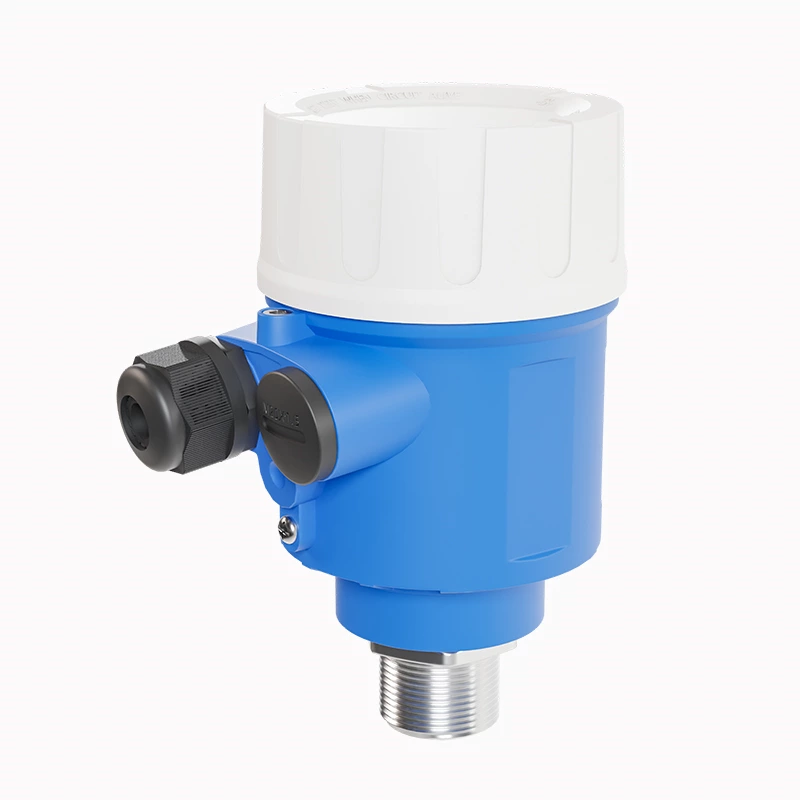
Quick product selection
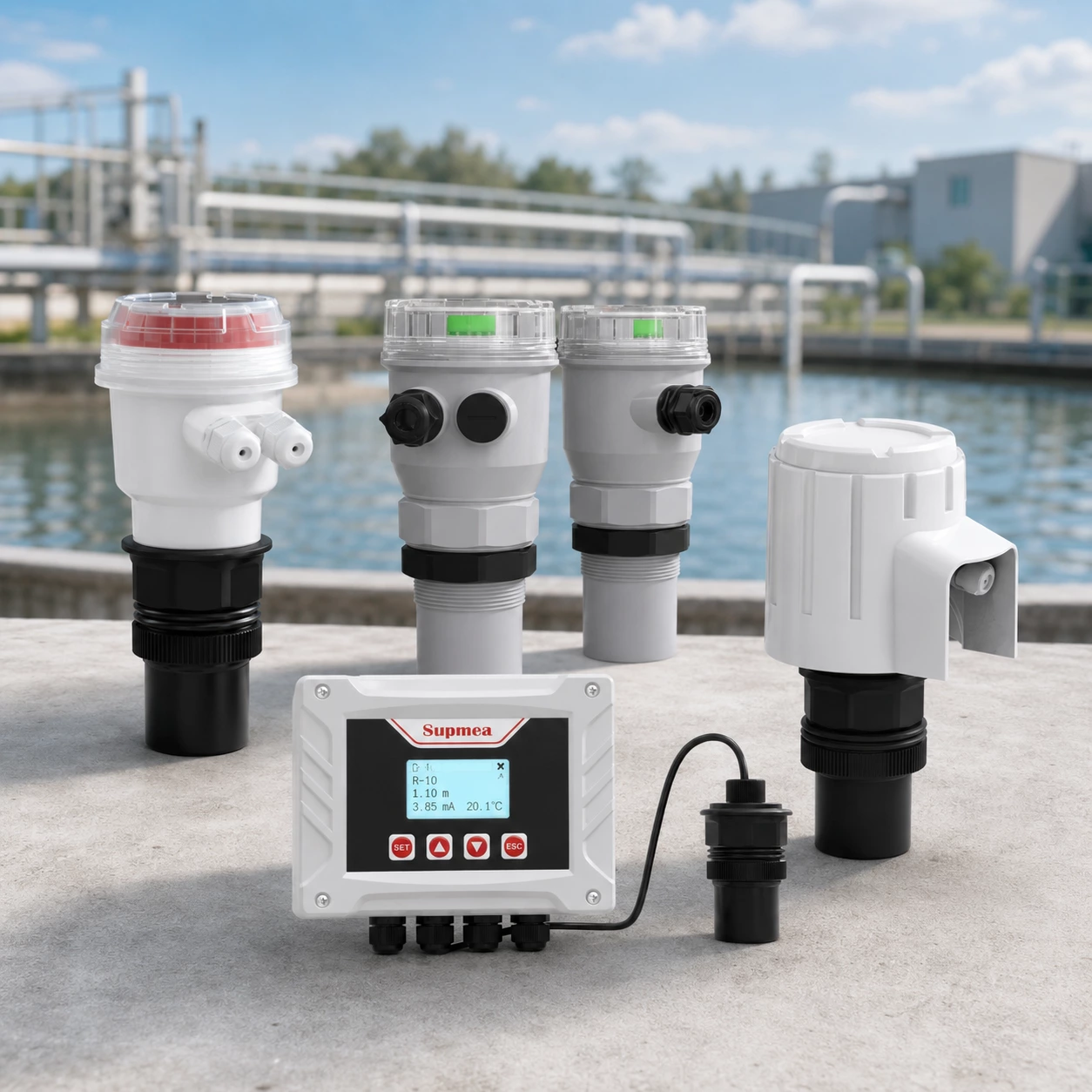
Find the right instrument for your application.
How ultrasonic level transmitter work
Applications & Industries
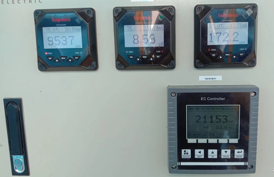
Multi-Parameter Water Quality Monitoring for a Building Project in Dubai
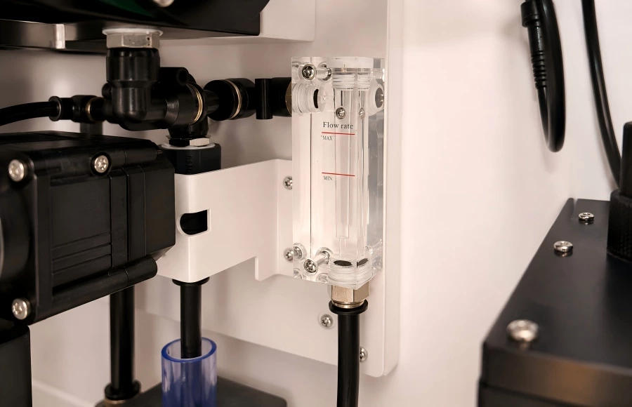
Integrated Flow and Water Quality Monitoring for an RO System in Indonesia
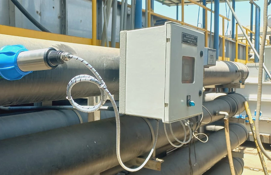
Inline Wastewater Turbidity Monitoring for a Treatment Pipeline in Peru
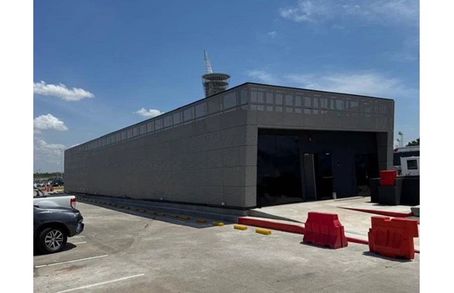
Supmea Multi-Parameter Monitoring Supports Water Treatment at an International Airport in Argentina
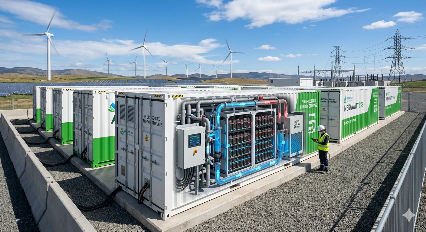
Related Products
Discover our most trusted process instruments for water and wastewater applications. Designed for reliable measurement, intelligent monitoring, and efficient process control across every stage of the treatment cycle.
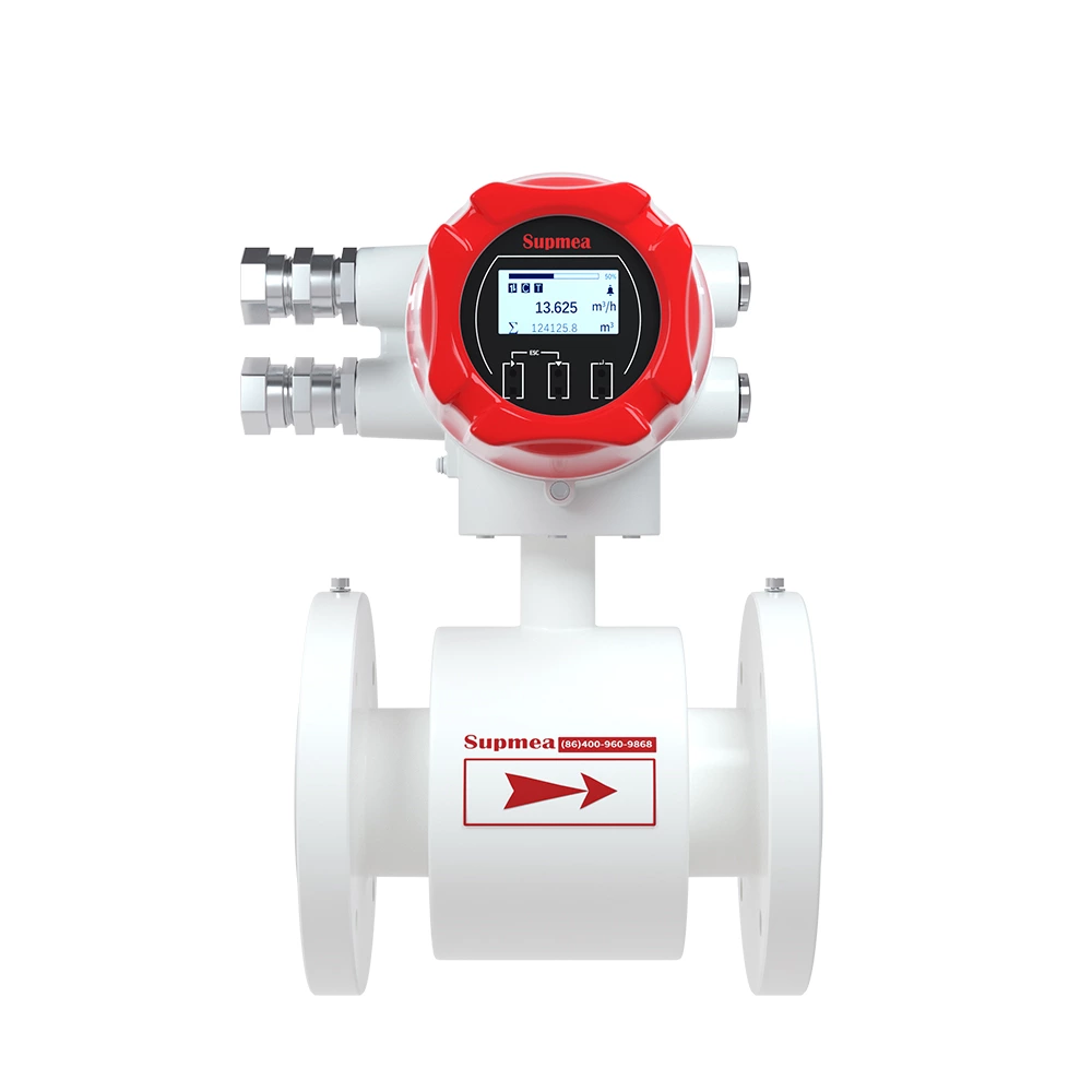
LDG-SUP-A100D Explosion-Proof Electromagnetic Flowmeter
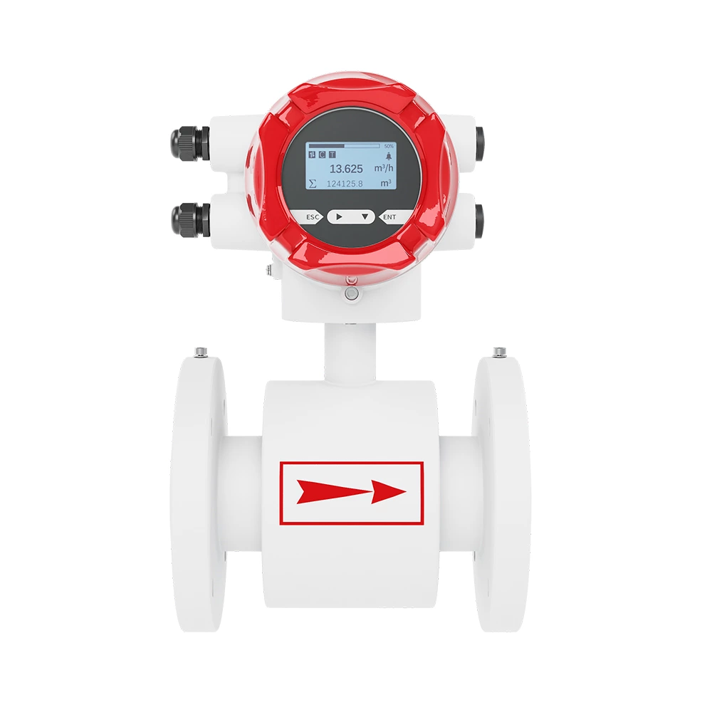
LDG-SUP-A100 Electromagnetic Flow Meter — High-Accuracy Conductive Liquid Measurement
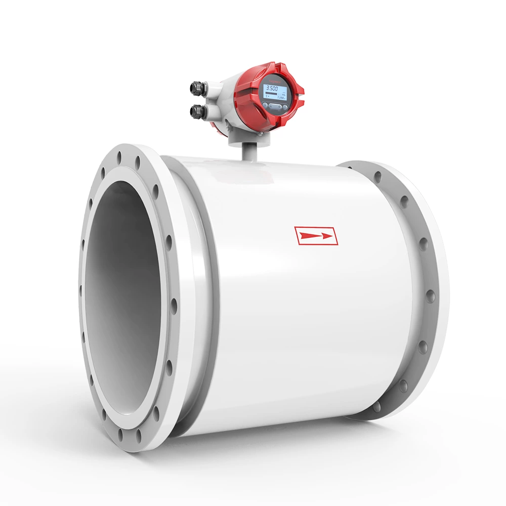
LDG-SUP Electromagnetic Flowmeter: Precision Flow Measurement for Demanding Industrial Applications
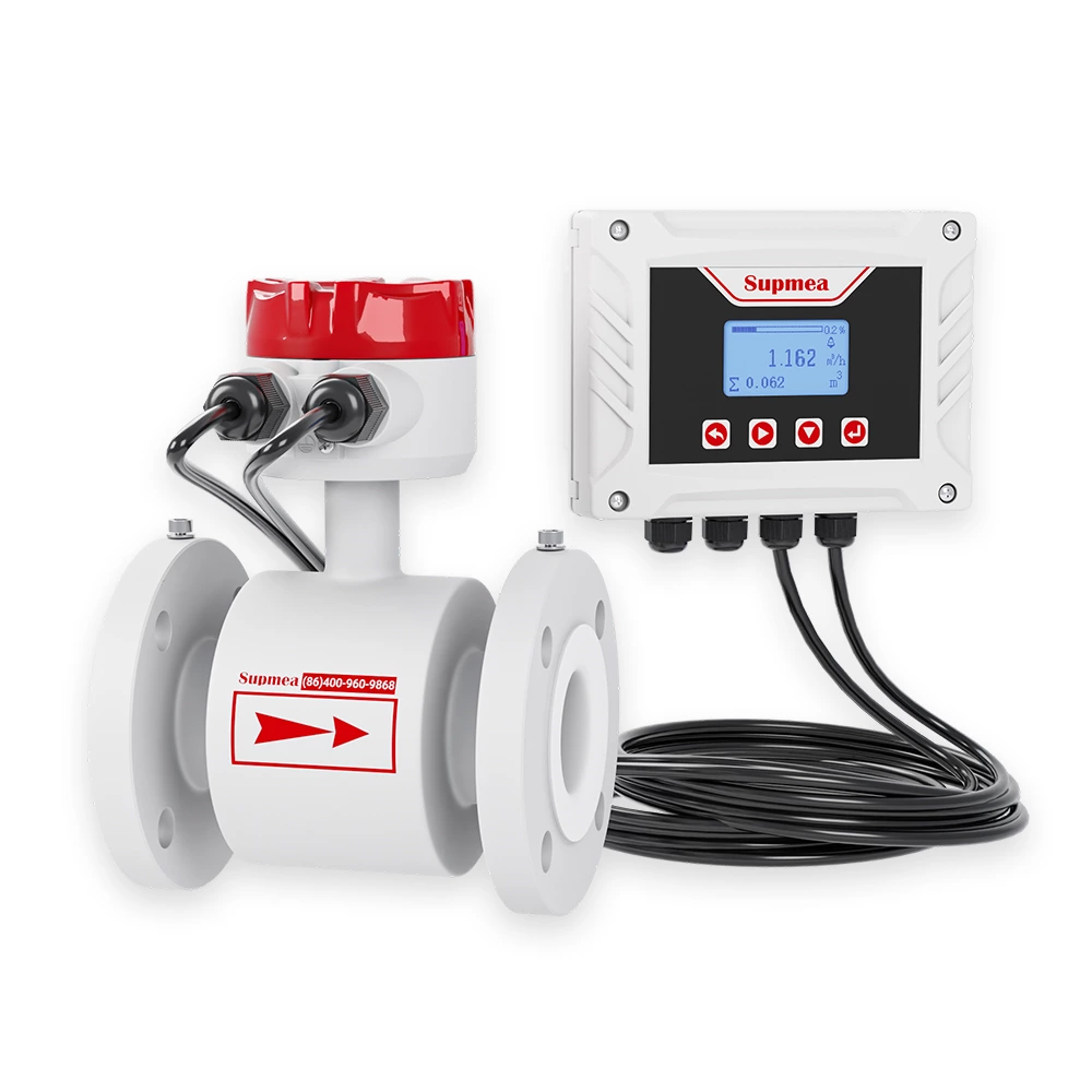
SUP-LDG Remote type electromagnetic flowmeter
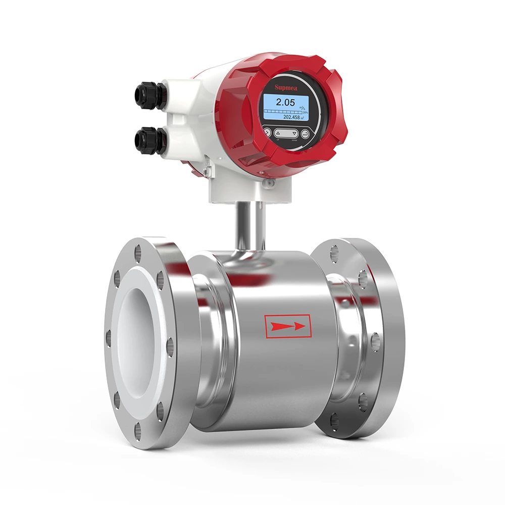
SUP-LDG Stainless steel body electromagnetic flowmeter
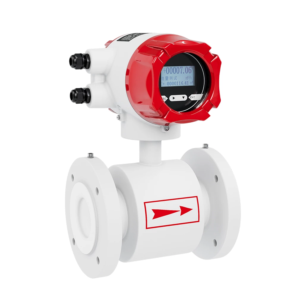
SUP-FMC400 Low Conductivity Electromagnetic flow meter
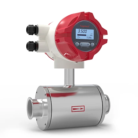
SUP-LDG Sanitary electromagnetic flowmeter for food processing
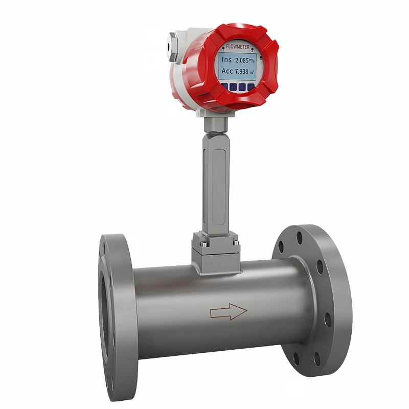
SUP-LUGB Vortex flowmeter without temperature & pressure compensation
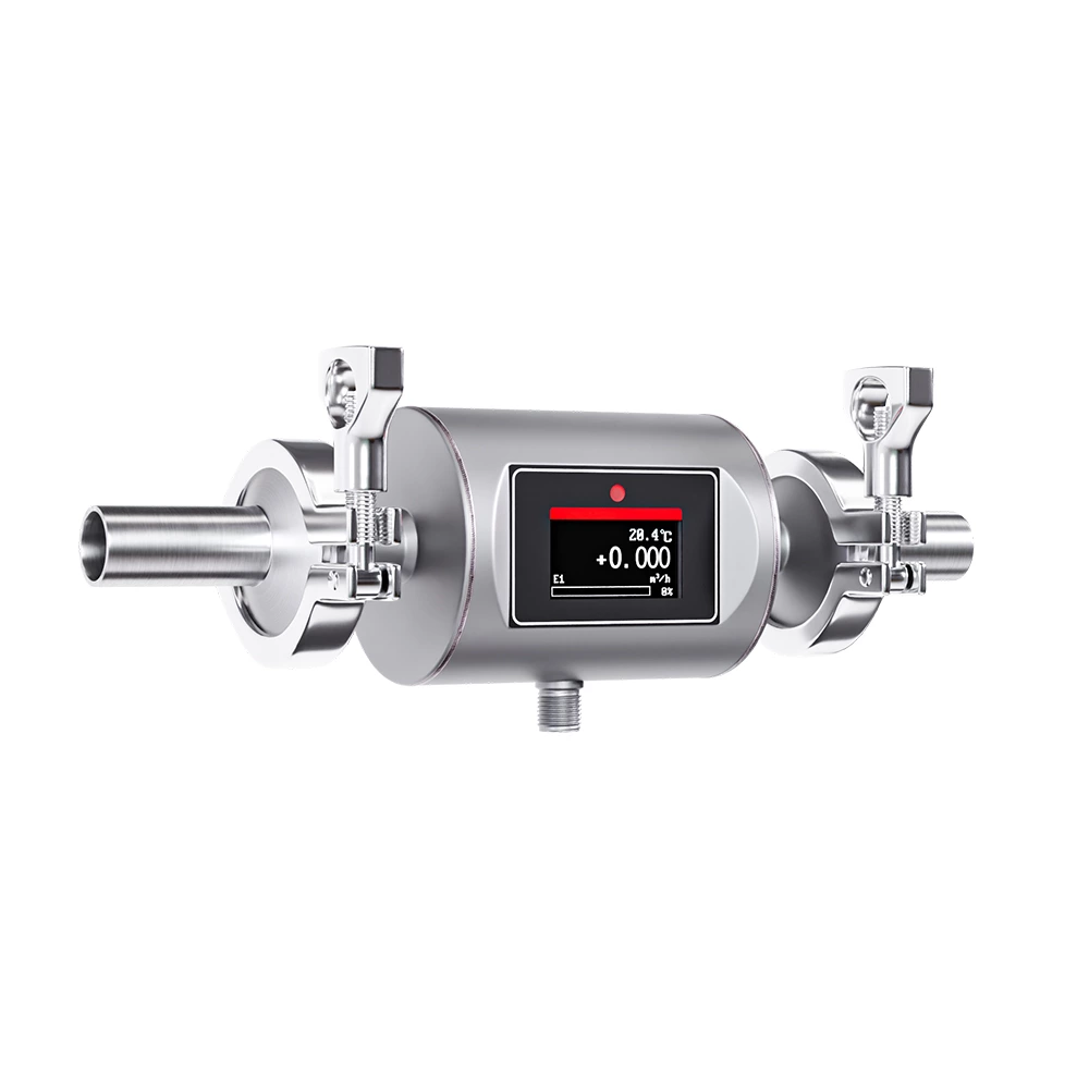
SUP-FMX240 Compact Electromagnetic Flow Meter—Precision Flow Measurement in a Space-Saving Design
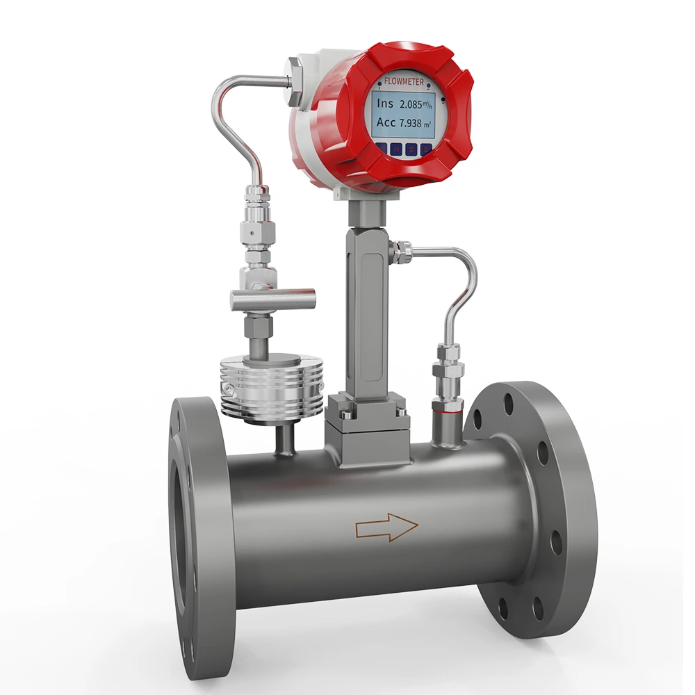
SUP-LUGB Vortex flowmeter with temperature & pressure compensation
Frequently Asked Questions
What is an ultrasonic level transmitter?
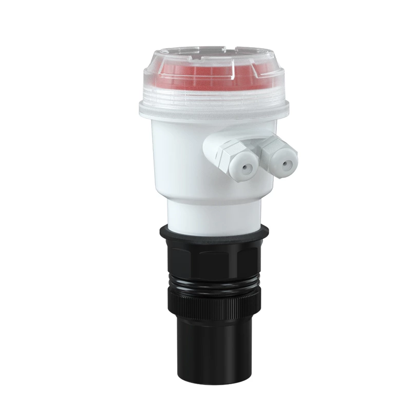
An ultrasonic level transmitter is a non-contact instrument that emits ultrasonic pulses toward a liquid or material surface. It calculates the level or distance from the time required for the reflected echo to return to the sensor.
What media can Supmea ultrasonic level transmitters measure?
They can be used for many liquids and suitable solid materials when a stable reflective surface and clear acoustic path are available. SUP-JFC is designed specifically for measuring underwater sludge interfaces or sludge thickness.
Which model is suitable for short-range measurement?
SUP-ZPM is designed for short measuring ranges of 1 m or 2 m. Its blind zone is ≤0.06 m for the 1 m version and ≤0.15 m for the 2 m version.
Which model provides the widest standard measuring range?
Among the general ultrasonic level transmitters on this category page, SUP-MP offers selectable ranges up to 30 m. SUP-JFC provides standard sludge-interface ranges up to 20 m and longer customized ranges.
What is the difference between integrated and remote ultrasonic level transmitters?
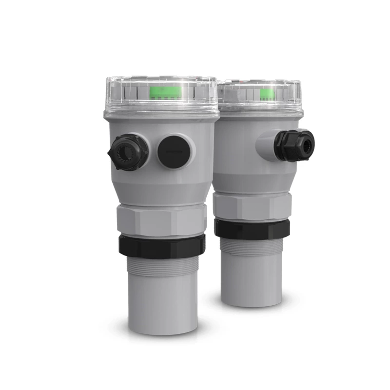
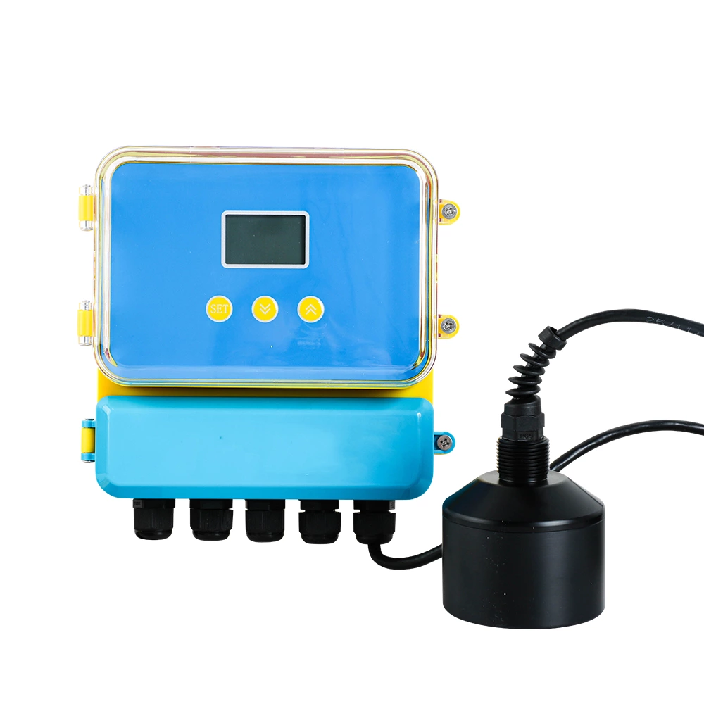
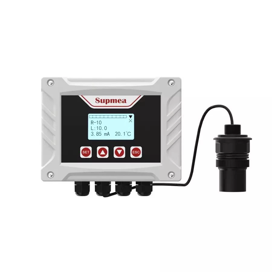
An integrated transmitter combines the display, electronics and transducer in one unit. A remote model separates the converter from the sensor, making it more suitable when the measurement point is difficult to access or the display should be installed in a protected location.
What output signals are available?
Depending on the selected model, available signals include 4–20 mA, RS485 Modbus-RTU, HART, voltage outputs, RS232 and relay alarms. Not every output is available on every model, so the required signal should be confirmed during model selection.