
Ultrasonic Level Transmitter: Installation, Maintenance, Application
An ultrasonic level sensor is a remarkable tool used for measuring the level of target solids and liquids in an industrial environment. Today, this post guides you to know this level measurement with detailed descriptions and walks you through how to install it for measuring different targets.
What is an ultrasonic level transmitter?
An ultrasonic level transmitter is a highly effective device designed to measure the level of liquids, solids, or slurries in tanks, silos, and other containers. It leverages ultrasonic waves with high-frequency sound waves ranging from 20 kHz to 200 kHz that are beyond human hearing to provide accurate level readings.
This non-contact measurement technology is widely used across industries for its reliability and versatility.
How does an ultrasonic level transmitter work?
To complete a precise measurement, its components cooperate tidily and organizedly inside its casing body:
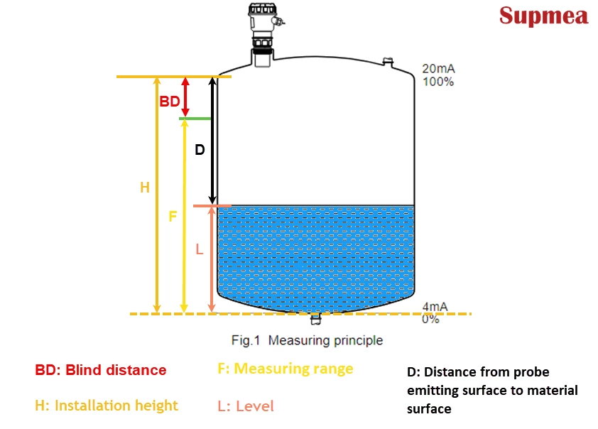
1. Emission of Ultrasonic Waves: The transmitter sends a burst of ultrasonic waves downward from a transducer toward the material's surface.
2. Echo Detection: These waves reflect off the surface and return to the transducer, which serves as both a sender and receiver.
3. Time-of-Flight Calculation: The device measures the time taken for the echo to return. Using the speed of sound in air (approximately 343 m/s at 20°C, adjusted for temperature, humidity, and pressure), the distance is calculated with the formula:
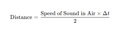
Note: The division by 2 accounts for the round trip of the wave.
4. Level Determination: The level is derived by subtracting the measured distance from the known distance between the transducer and the container's bottom.
5. Transducer: Converts electrical signals into ultrasonic waves and captures the returning echoes.
6. Electronics Unit: Processes data, applies environmental corrections, and converts it into a readable level measurement.
7. Display/Output: Features a digital display or outputs a signal (e.g., 4-20 mA) for integration with control systems.
How to install an ultrasonic level transmitter?
Installing an ultrasonic level transmitter correctly is crucial for accurate measurements of liquids, solids, or slurries in tanks, silos, and wells. These non-contact ultrasonic level sensors rely on proper positioning to ensure reliable performance and avoid false echoes.
Based on the changes of the measured targets and working scenarios, the approaches and tips for the ultrasonic level measurement installations vary. Just take the following details as references for the final installation:
Before the installation:
Before exploring every essence of installation, here are some tips that need to be taken into consideration to enhance safety and accuracy:
- Choose a threaded or flange mounting approach based on the liquid or solid container type.
- Better to install in the well-ventilated areas to prevent overheating.
- Direct sunlight, temperature over 60°C, humidity over 85%, electromagnetic interference, vibrations, condensation, or environments with dust, steam, or corrosive gases should be avoided.
- Ensure the probe's emitting surface is perpendicular to the measured surface if possible.
- Use tools like universal flanges for installation in challenging setups.
Installing ultrasonic level sensors for measuring liquids
Ultrasonic transmitters excel in liquid level monitoring. Here's how to install them in various tank configurations:
1. Flat-top tank
For installing the ultrasonic water measurements on the flat-top tank, here are various choices based on the different working environments. Below are the approaches:
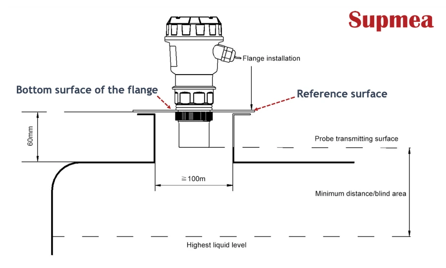
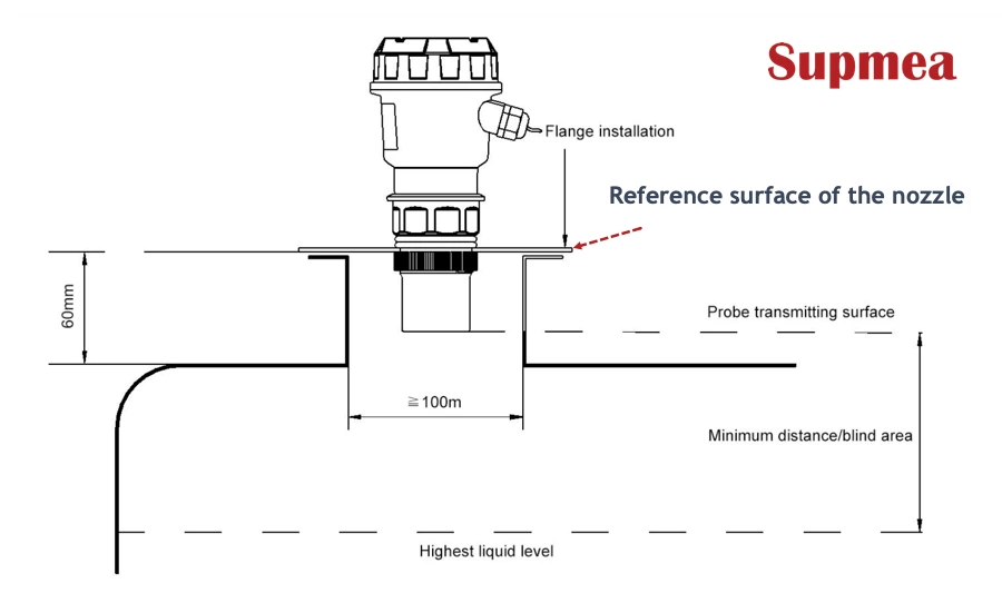
Short-nozzle installation
Most of the time, a flat-top tank has a short nozzle, whereas the reference surface of the nozzle and the bottom surface of the flange are the same.
If the nozzle's length is under 60mm, the inner diameter is bigger than 100 mm with the inner wall being flat and no burrs or protusions, then the level sensor is suitable to be mounted on the short nozzle. Just be shown as below:
No-nozzle installation
Operators can install the level probe on the flat-top container directly if there is a circular opening, on condition that the flange or universal joint can be fixed firmly. Note that the probe's surface ought to be below the reference plane for normal measurement.
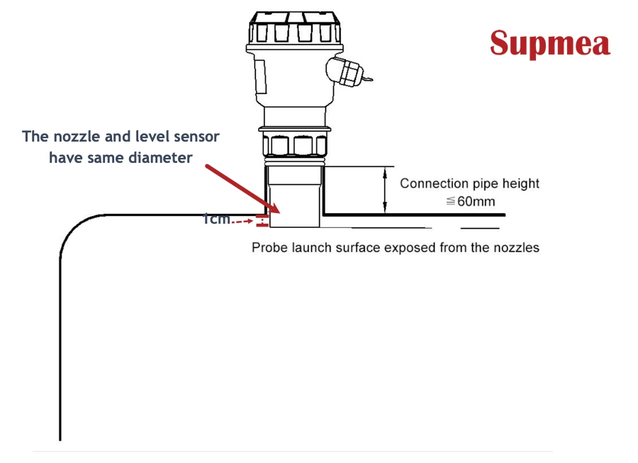
Threaded-nozzle installation
Once the nozzle and the probe share the same diameter parameter, the probe can be placed on the nozzle straightforwardly. Note that the probe's surface must be 1cm longer than the nozzle, or it cannot measure the water level properly.
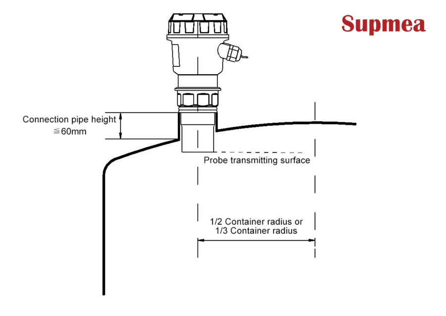
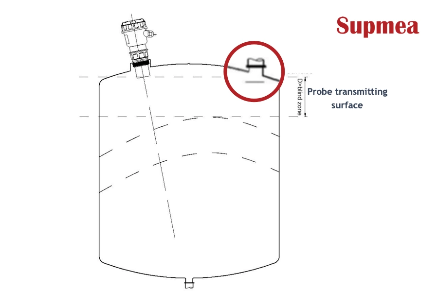
2. Arched tank top
Since the ultrasonic level probe has been widely used in liquid and solid level measuring, it's common for us to explore how to install it in an arched tank top environment.
The dome-shaped tank top looks like a convex lens, so if the level measurement is taken at its center point, the level probe receives all false echoes.
The right way is to install the sensor at 1/2 or 2/3 of the radius of the tank top on the premise of satisfying a certain distance from the tank wall, then the ultrasonic meter can read and respond with correct data. Just as shown below:
Install the level sensor on the threaded nipple-dome roof:
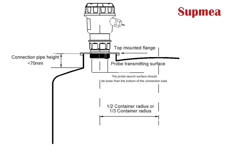
Install the level measurement on the flange-dome roof:
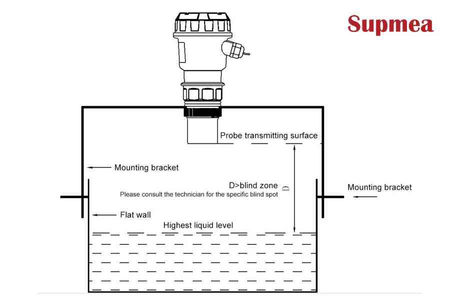
3. Open tank
When it comes to the open tank, a bracket is necessary for mounting the level sensor configured with an ultrasonic probe.
At this moment, attention should be given to the bearing capacity of the bracket and the distance between the sensor and the tank wall simultaneously.
Make sure the bracket is solid and hard enough, and corrosion resistance is indispensable, as if you install the level measurement in outside areas.
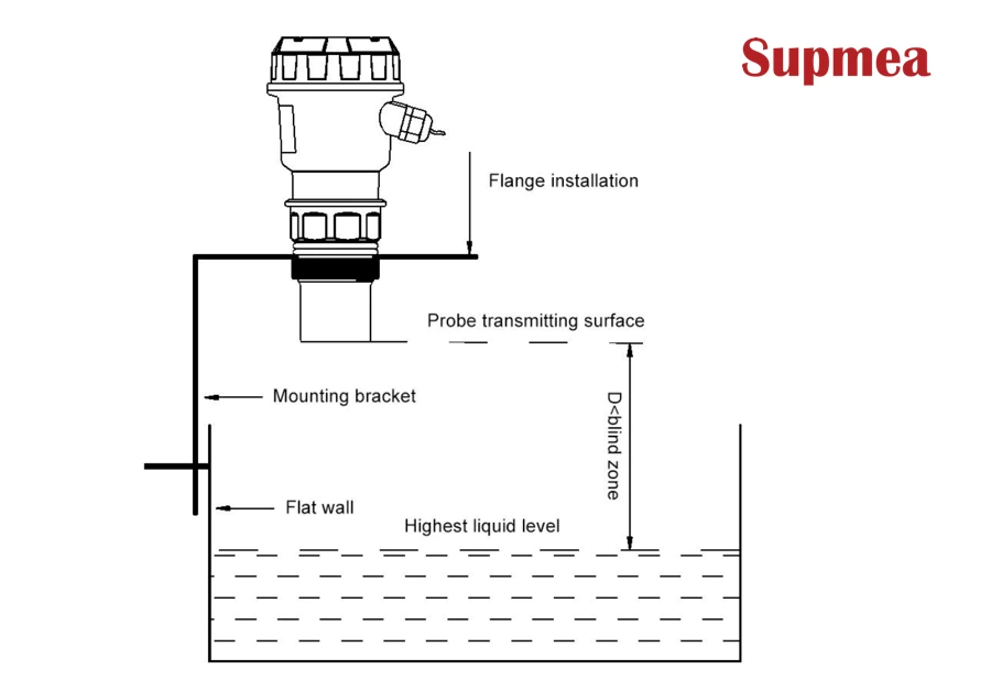
If the open liquid has no pivot, you can place the level sensor in the middle of the tank.
4. Installation of drainage and an ordinary well
The drainage shaft and wellhead wells are almost narrow, and the borehole wall is uneven, making the level measurement challenging. This issue can be fixed by installing a nozzle or an entire measuring sleeve on the wells for the level meter mount.
Once the sensor is placed in the nozzle, the blind area will increase by about 50 ~100%, so this factor should be taken into consideration when this installation approach is selected.
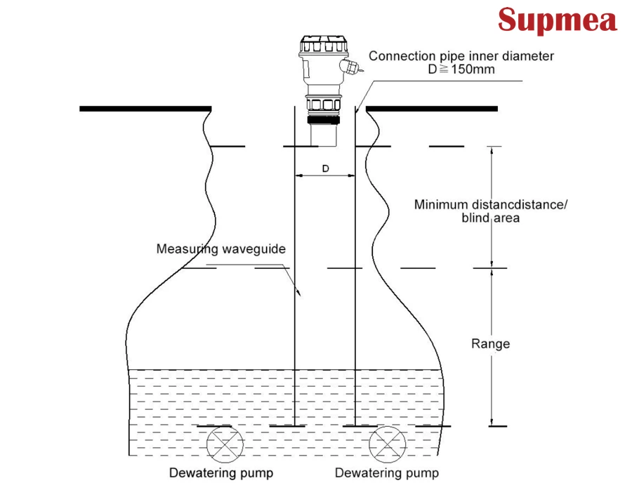
For ordinary wells, including water source wells and deep water wells with small diameters, a measuring sleeve can be installed to mount the level sensor for measurement.
In the installation, the inner side of the measuring sleeve should be smooth, like the PVCor PE material, with the inner diameter bigger than 150mm under the measuring range of 4 meters.
Installing ultrasonic level sensors for measuring solids
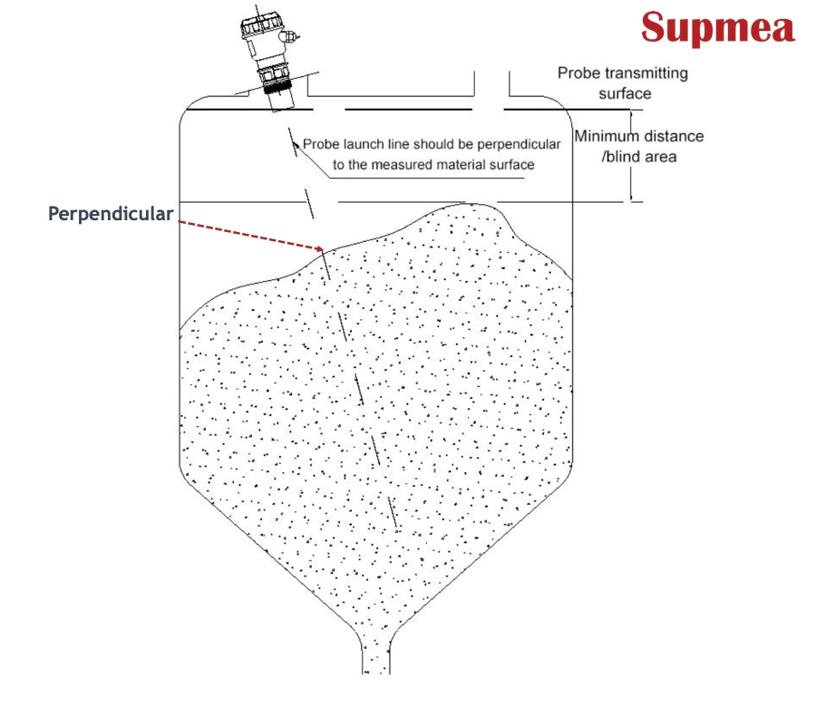
1. Flange mounting
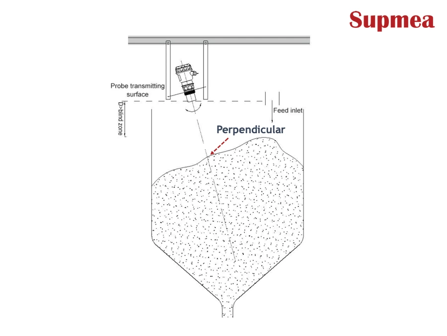
Just like the liquid level measurement, the solid level measurement can adopt the butt flange installation of the container nozzle. Since the surface of the measured solid is not plane, the surface of the probe must be perpendicular to the solid's surface.
If the probe is retracted into the nozzle, the measured data will be incorrect. To troubleshoot this, a universal flange should be selected so that as long a the flange is rotated, the probe surface keeps aligned with the reflecting surface of the measured solid.
2. Threaded pipe installation
The level probe can also be installed in a threaded nipple with its probe surface surpassing 2cm away from the nipple reference surface.
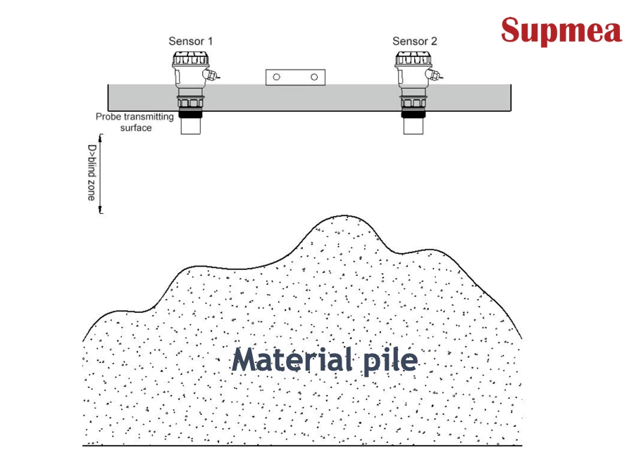
3. Frame type installation
Gantry frame type installation is suitable for the open tank of solid measurement, and the axis of the nozzle must keep in line with the outlet container or perpendicular to the surface of the measured solid.
When it comes to the installation of the open-air material pile, the number of sensors should be more than two for the comprehensive and accurate level measurement, where the sensors can be fixed on the lifting frame, and their probes should be aligned with the surface of the medium.
Nozzle maintenance tips
The nozzle should not be intrusive to the measured medium, or it gets dirty, which damages the nozzle surface and shortens its lifespan.
Once the installation is finished, the wiring and final setup can be done to initiate the level measuring:
- Connect via (18-28)VDC power, with options for 4-20mA output, RS485 communication, or relays.
- Ground properly to prevent shocks, and use surge protectors for lightning-prone areas.
- After installation, calibrate for temperature compensation and test for echoes using the device's self-checking features.
How to maintain an ultrasonic level sensor?
Keeping the ultrasonic level transmitter in top shape is key to accurate readings in liquid and solid level measuring. Here’s a straightforward guide on how to maintain an ultrasonic level measurement based on common practices.
Regular simple check
Look it over monthly for scratches, rust, or gunk on the transducer, and wipe it with a dry cloth if needed on a regular basis.
Sensor cleaning
Every few months, gently clean the emitting face with a soft brush or warm water to clear dirt, then dry it off.
Verify mounting and alignment
Make sure the transmitter is securely mounted and properly aligned to avoid signal interference or measurement errors.
Perform calibration checks
Periodically compare the transmitter’s readings with reference measurements and recalibrate if necessary to maintain accuracy.
Inspect for physical damage
Look for cracks, dents, or any physical damage on the unit that could affect its performance.
Check for moisture and condensation
Ensure the housing is sealed and dry to prevent moisture ingress, which can cause malfunctions.
Update firmware when needed
Install any manufacturer-recommended firmware updates to improve performance and fix known issues.