| Nominal diameter |
DN15, 20, 25, 32, 40, 50, 65, 80, 100, 125, 150, 200, 250, 300; insertion type DN300–DN1000 (above DN1000 by agreement) |
| Nominal pressure (wafer/clamping flange) |
DN15–DN50: ≤4.0 MPa; DN65–DN100: ≤2.5 MPa; DN125 and above: ≤1.6 MPa |
| Nominal pressure (flange connection) |
DN15–DN50: ≤2.5 MPa; DN65–DN300: ≤1.6 MPa |
| Medium temperature |
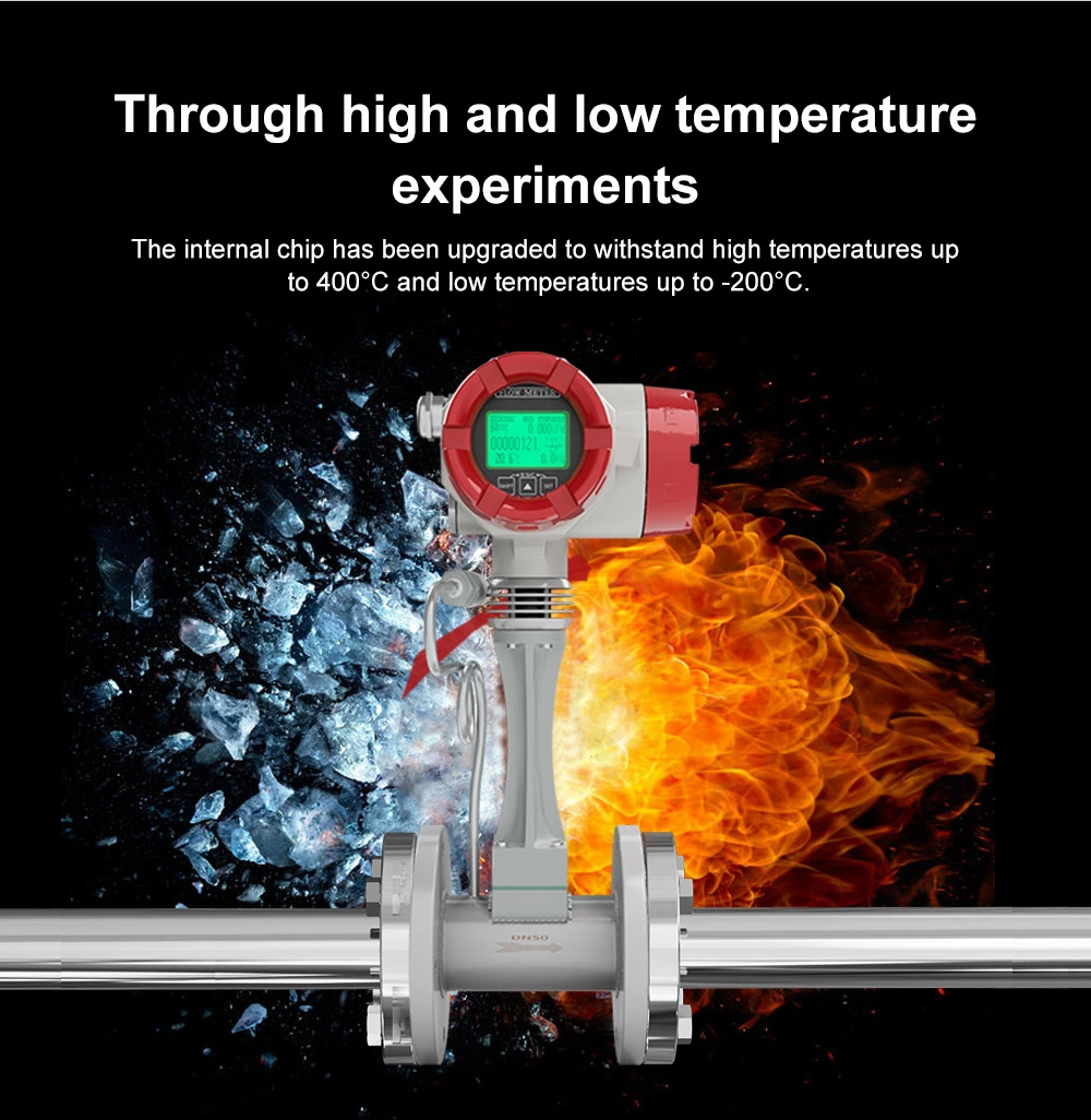
Standard: -40~100°C; KST-M: -40~250°C; KST-HC: -40~330°C (by agreement) |
| Environmental conditions |
Ambient temperature: -20~55°C; relative humidity: 5%~90%; atmospheric pressure: 86–106 kPa |
| Materials |
Body: 304 stainless steel (other materials by agreement); integrator housing: die-cast aluminum |
| Allowable vibration acceleration |
Piezoelectric type: 0.2g |
| Accuracy |
±1%R, ±1.5%R; insertion type: ±2.5%R |
| Rangeability |
1:6 to 1:25 |
| Supply voltage |
Sensor: DC +24V; transducer: DC +24V; battery-powered: 3.6V battery |
| Output signal |
Pulse output; 4–20mA current; RS485 (Modbus RTU protocol), etc. |
| Pressure loss factor |
Cd ≤ 2.4 (per JB/T 9249) |
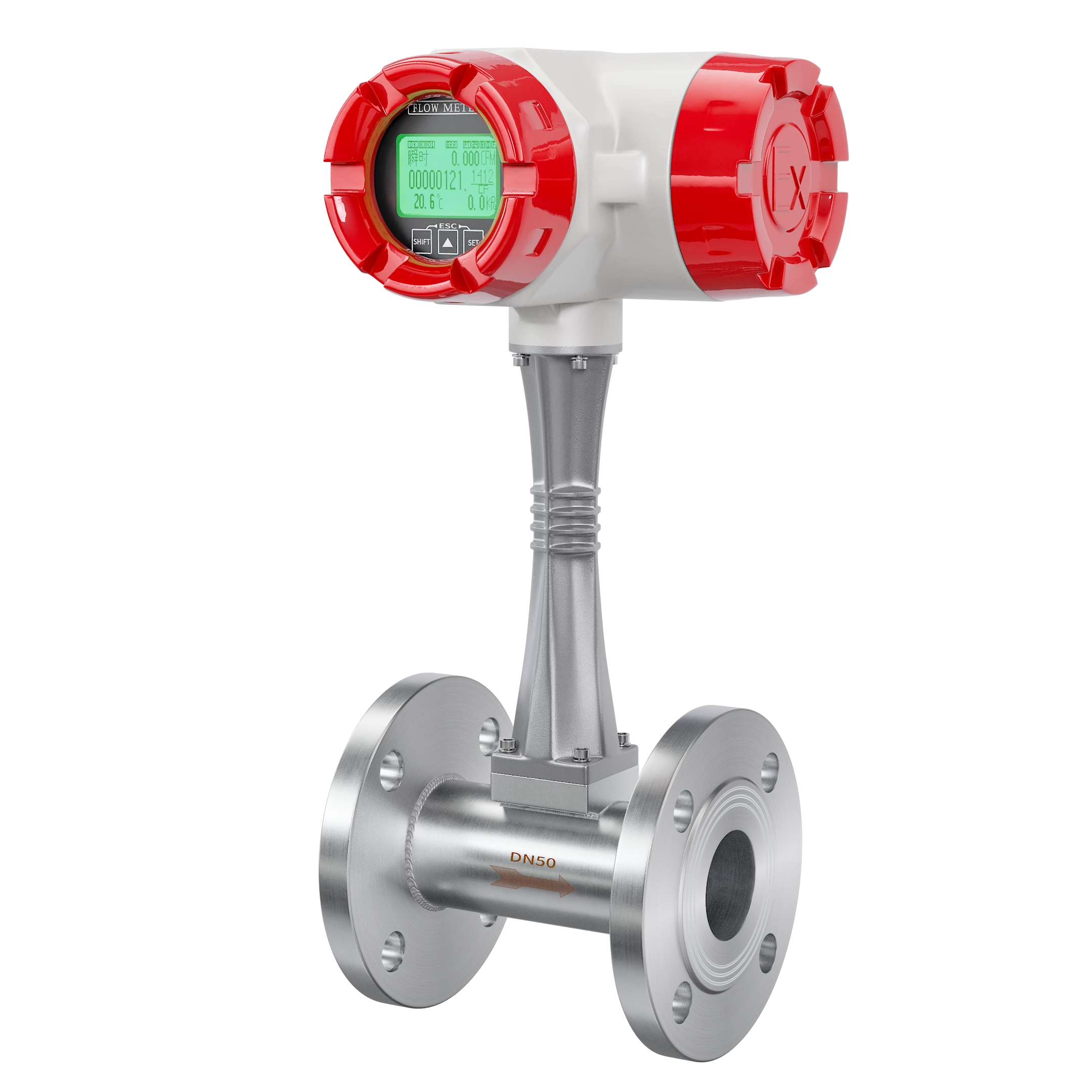
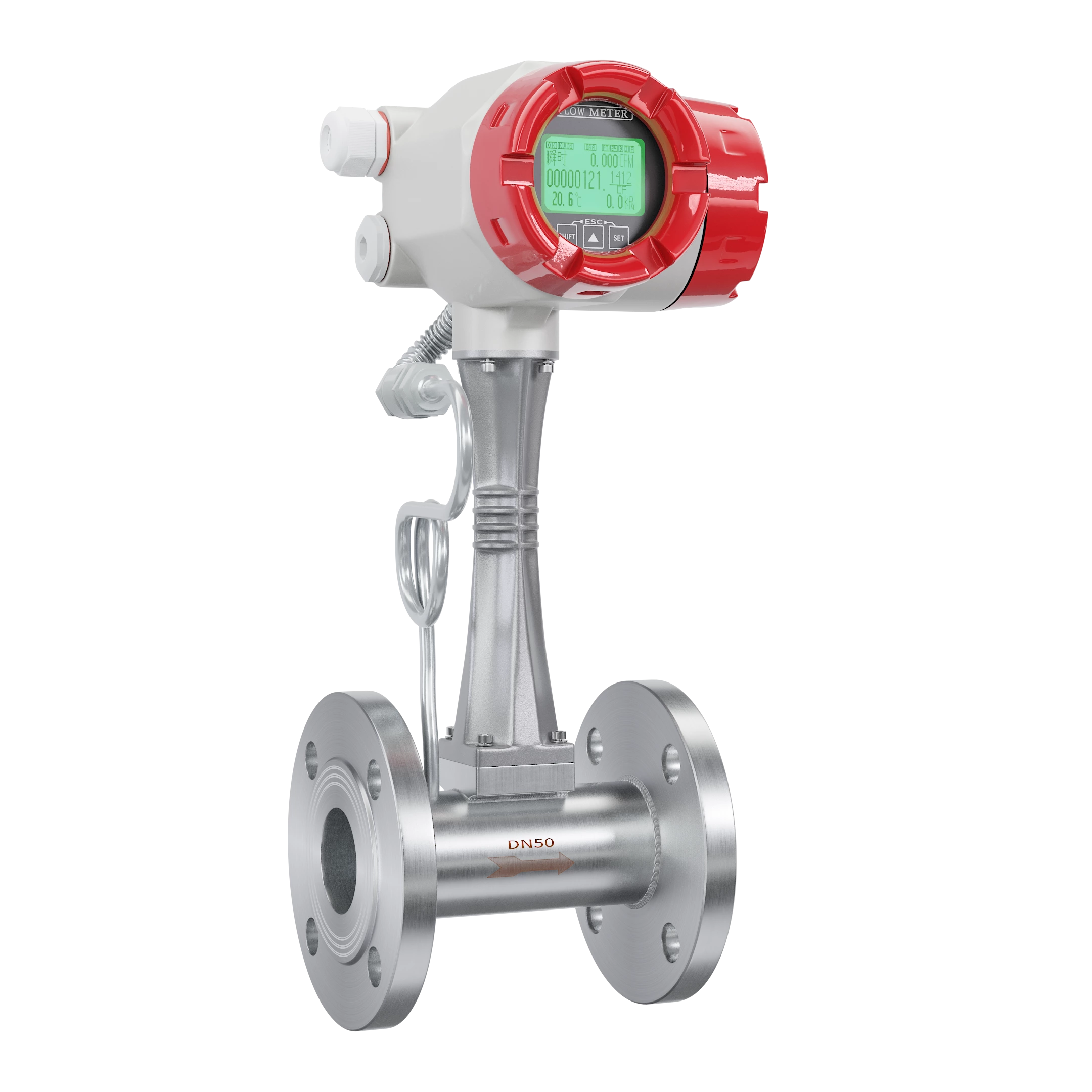
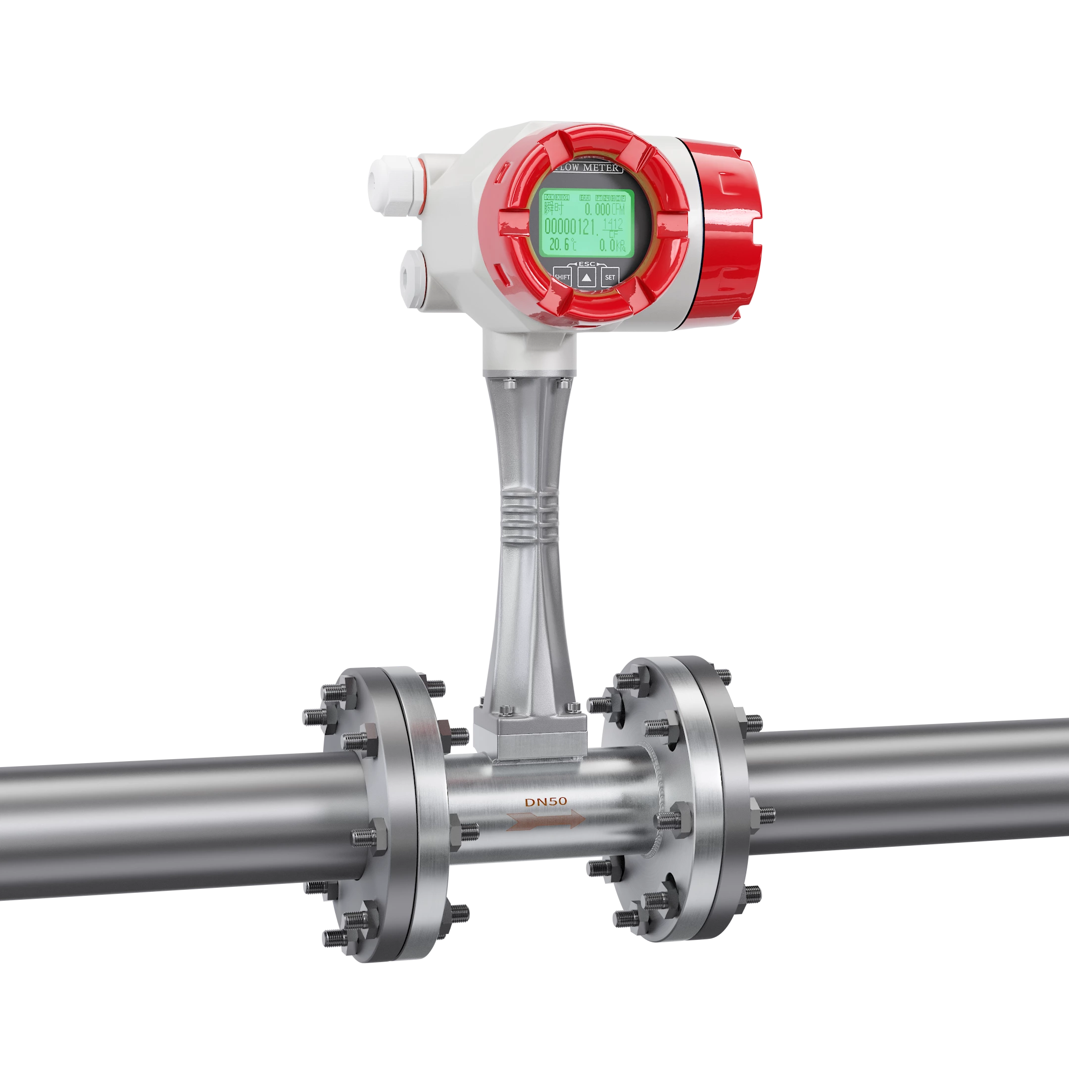
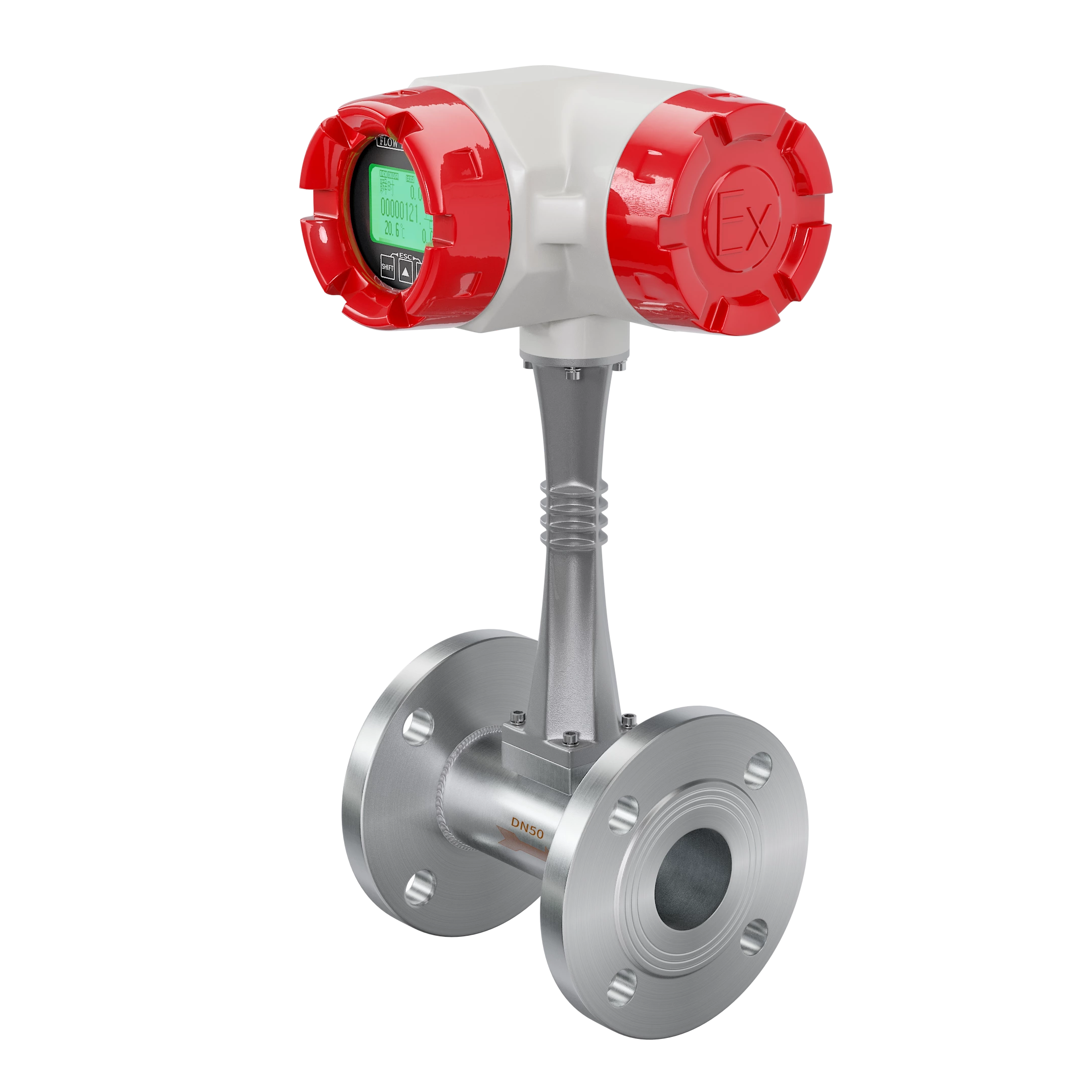
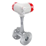
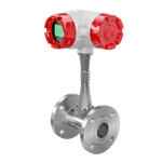
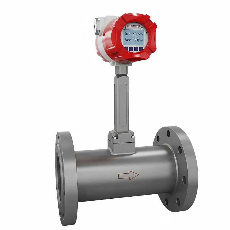
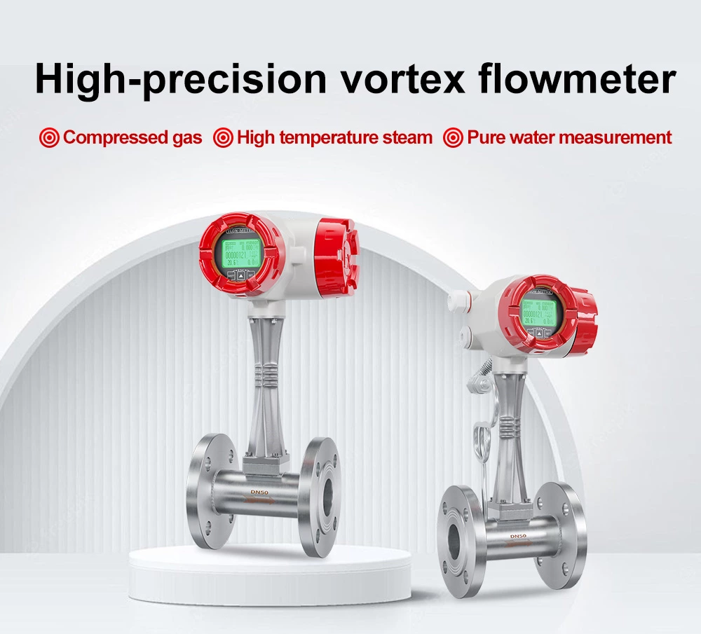
The LUGB-C is a velocity-type flow meter designed on the Karman vortex principle, mainly used for flow measurement and control of media in industrial pipelines — gas, steam and liquid.
Depending on configuration, the LUGB-C vortex flow meter can measure medium temperature, pressure, instantaneous flow and cumulative flow, and provides pulse output, 4–20mA analog signal output, RS485 communication (Modbus RTU protocol) and GPRS Internet functions.
It is widely used in heat supply, gas supply, chemical, environmental protection, metallurgy, textile, steel, pharmaceutical, papermaking and drainage industries for the measurement and control of superheated steam, saturated steam, compressed air, gases (oxygen, nitrogen, hydrogen, etc.), water and liquids (such as alcohol and benzene-class liquids).
High Accuracy Across a Wide Range
Accuracy of ±1%R and ±1.5%R for pipe-mounted types (±2.5%R for insertion types), with rangeability from 1:6 up to 1:25 — covering both normal and extended flow ranges.
Built for Demanding Industrial Media
Measures steam, gas and liquids of lower viscosity. Standard medium temperature range -40°C to 100°C; Wafer-type pressure rating up to 4.0 MPa.
Multiple Output Signals & Communication
Pulse output, 4–20mA analog output, RS485 (Modbus RTU) and GPRS — easy integration with DCS, PLC and SCADA systems.
Flexible Power Options
DC +24V for sensor and transducer, or 3.6V battery-powered operation for locations without external power.
Robust Construction
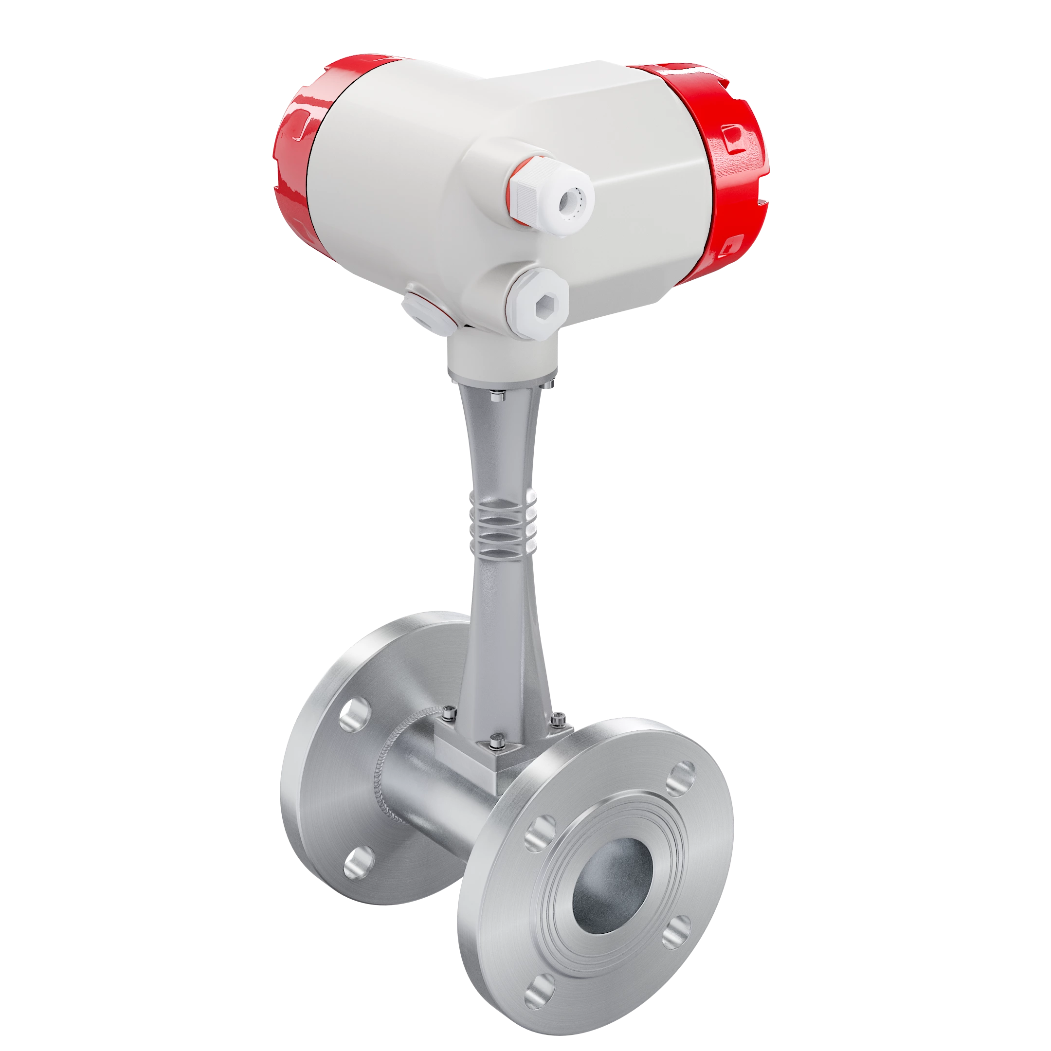
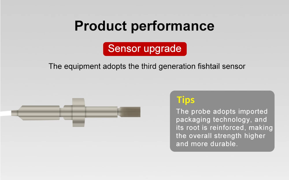
304 stainless steel flow body (other materials by agreement) with a die-cast aluminum integrator housing; piezoelectric sensor withstands vibration acceleration up to 0.2g.
Temperature & Pressure Compensation Available
Optional integrated temperature and pressure compensation converts working-condition volume flow into standard volume or mass flow for trade metering.
Low Pressure Loss
Pressure loss factor Cd ≤ 2.4, complying with the JB/T 9249 standard.
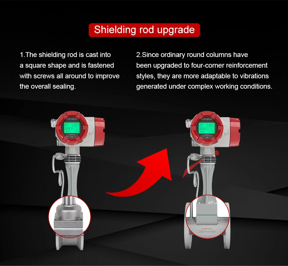
The LUGB-C vortex flow meter works on the Karman and Strouhal vortex theory, specializing in the measurement of steam, gas and liquids of lower viscosity.
When the medium flows through the bluff body (vortex generator) inside the meter, vortices are alternately formed on both sides with opposite directions of rotation. The vortex frequency is directly proportional to the medium velocity. The sensor head measures the number of vortices, from which the medium velocity is calculated — combined with the meter diameter, the volume flow is obtained.
Formulas:
F = St · V / m d (vortex frequency)
Q = 3600 · F / K (instantaneous volume flow, m³/h)
M = Q · ρ (instantaneous mass flow, kg/h)
Where
F = vortex frequency (Hz);
St = Strouhal constant (dimensionless);
V = mean fluid velocity (m/s);
m = ratio of the bluff-body side flow area to the cross-sectional area (dimensionless);
d = upstream face width of the bluff body (m);
D = inside diameter of the meter (m);
Q = instantaneous volume flow (m³/h);
K = meter coefficient (pulses/m³);
M = instantaneous mass flow (kg/h);
ρ = fluid density (kg/m³).
Note: the K coefficient corresponds to one diameter and should be calibrated in practice.
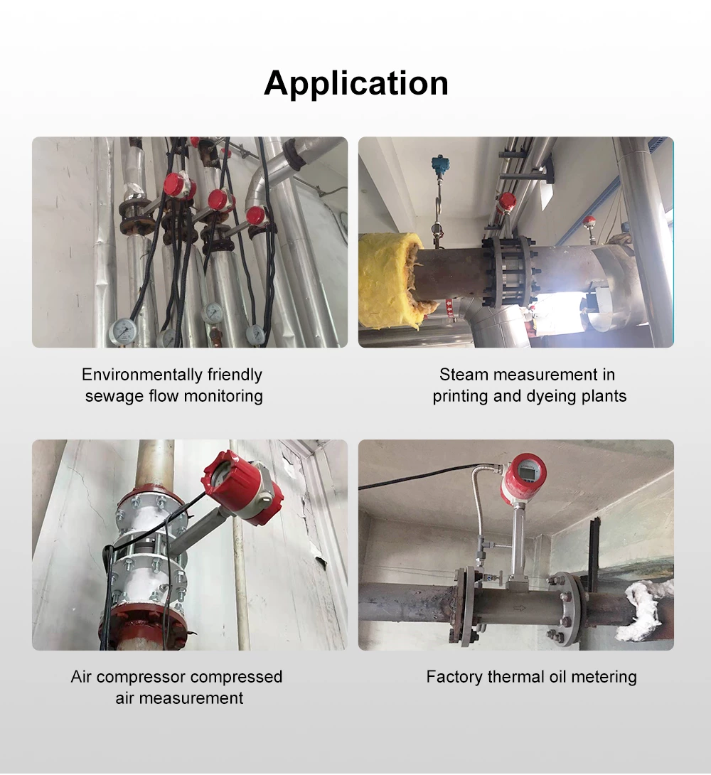
The LUGB-C vortex flow meter serves a wide range of industries:
• Heat supply & power heating — superheated and saturated steam metering
• Gas supply & compressed air systems — compressed air, oxygen, nitrogen, hydrogen and other gases
• Chemical & petrochemical — flow control of process gas and liquid
• Pharmaceutical & food-grade processes
• Steel & metallurgy — cooling water and gas metering
• Environmental protection, textile, papermaking and drainage
• Boiler steam measurement and energy auditing
Typical measured media: superheated steam, saturated steam, compressed air, oxygen, nitrogen, hydrogen, natural-type gases, water, alcohol and benzene-class liquids.
Q:Why does the flow reading or frequency fluctuate a lot on site?
Check the following causes:
(a) The straight pipe run does not meet the requirements — for gas measurement, ensure at least 10D upstream and 5D downstream, or change the installation position.
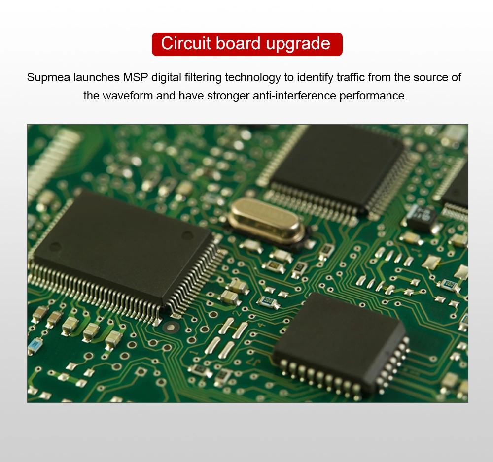
(b) Electromagnetic interference on site — enhance the filtering function and lower the sensitivity via the DIP code switch.
(c) The on-site flow is too small and below the meter's lower limit — e.g. a DN300 insertion gas meter has a lower limit of 1500 m³/h; below the lower limit the reading is no longer linear. Increasing flow by changing the meter factor is possible but not recommended.
(d) A similar situation can occur when measuring the pulsating flow of a liquid.
Q:The meter shows flow when the pipeline is static — why?
This is mostly caused by on-site pipeline vibration. It can be alleviated or eliminated by adding damping measures or reducing the instrument sensitivity.
Q:The displayed flow differs greatly from the actual flow — what is the most likely cause?
In most cases this is a parameter unit setting problem. Verify the unit settings.
Q:Readings are inconsistent for the same working condition with a large difference — why?
Possible causes:
(a) The reference value used for comparison is wrong, or the working conditions differ — pipeline problems, straight pipe problems, vibration, etc.
(b) The parameters have been modified by the user.
(c) The flow rate is too low and below the lower limit, where the meter is non-linear. (d) For temperature & pressure compensation meters, a faulty temperature or pressure measurement.
Q:Why is there no flow signal output?
Check:
(a) The small-signal cut-off value is too large — modify it in the parameter settings.
(b) The power supply is not connected.
(c) The flow rate is very low and has not reached the signal trigger point.
(d) For 4–20mA output meters, the output was not configured before leaving the factory.