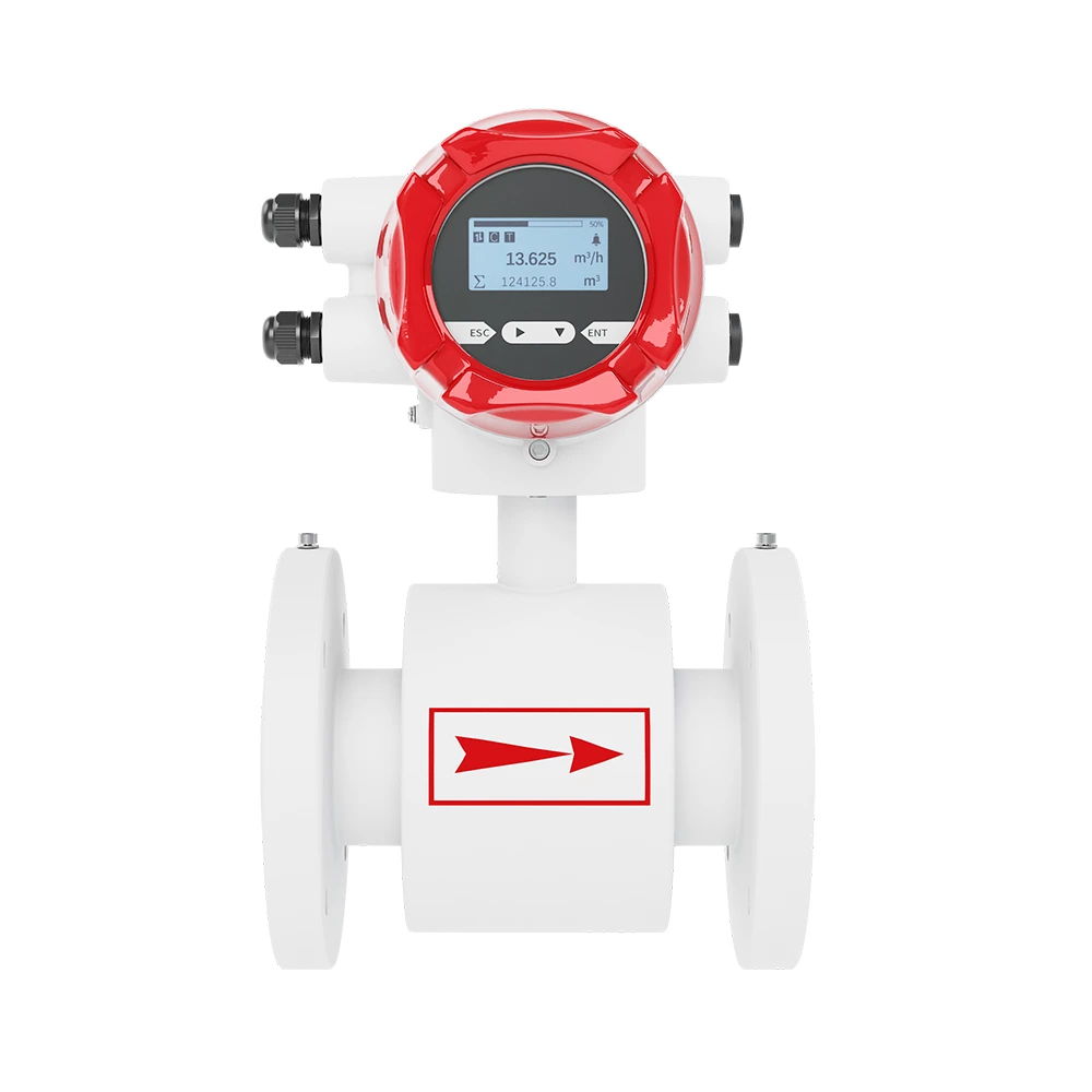
Introduction
* Electromagnetic metering pumps have only one moving part—the armature shaft. Generally speaking, the fewer moving parts, the more reliable the metering pump.
* Electromagnetic metering pumps are ideal for low-flow, low-pressure applications and offer excellent compensation for power supply voltage fluctuations.
* Compared to fixed-frequency, variable-stroke metering pumps, fixed-stroke pumps, through calibration, provide a known dosage per stroke. Therefore, the total dosage can be calculated (dosage = dosage per stroke * frequency).
* The total dosage is linearly proportional to frequency (50% frequency = 50% dosage). Control is via external pulse or analog control.
Technical Parameters
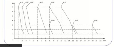
| Model |
Flow (L/h) |
Pressure (bar) |
Stroke frequency (times/min) |
Suction height (m) |
Power (W) |
Power |
Weight (kg) |
| -01-07-S |
1 |
7 |
120 |
2 |
25 |
220V.50HZ |
2.6 |
| -02-07-S |
2 |
7 |
120 |
2 |
25 |
220V.50HZ |
2.6 |
| -03-07-S |
3 |
7 |
120 |
2 |
25 |
220V.50HZ |
2.6 |
| -06-05-S |
6 |
5 |
120 |
2 |
25 |
220V.50HZ |
2.6 |
| -09-03-S |
9 |
3 |
120 |
2 |
25 |
220V.50HZ |
2.6 |
| -09-07-M |
9 |
7 |
160 |
2 |
50 |
220V.50HZ |
2.9 |
| -12-07-M |
12 |
7 |
160 |
2 |
50 |
220V.50HZ |
2.9 |
| -15-03-M |
15 |
3 |
160 |
2 |
50 |
220V.50HZ |
2.9 |
| -20-03-M |
20 |
3 |
160 |
2 |
50 |
220V.50HZ |
2.9 |
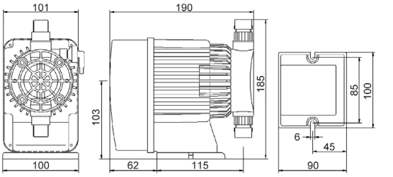
Installation Dimensions
Installation
The position for installing metering pump should be convenient for its connection with chemical agent tank and injection point. With waterproof and dust proof design, this pump can be used in outdoor place, but shall not be immersed into water for use. Make sure that the temperature is not over 40 ℃(104℉), otherwise it may be damaged.
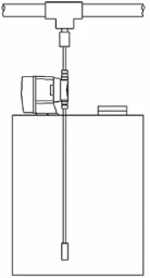
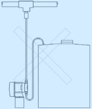
●Immersion installation (ideal installation). (See Fig. 1)
 |
 |
| × |
√ |
Fig. 1
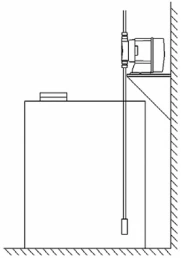
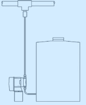
●Suction and lift installation. When suction head is less than 1.5m high and the solution’s specific gravity is not higher than that of water, this installation mode is preferred. When the solution’s specific gravity is high, please contact the manufacturer. (See Fig. 2)
Fig. 2
Note: Injection point must be higher than the top of solution supply tank to prevent feeding by gravity unless there is always appropriate back pressure of injection point. Anti-siphon valve shall be installed to prevent feeding by gravity.
2. Electrical Wiring
The metering pump has an accompanying cable that is 1.5m long. During installation, air switch is required between metering pump and power supply and specified wiring should conform to local electrical installation specifications.
 Note: Make sure that supply circuit has been powered off before wiring.
3. Control Wiring
●Manual metering pump
| Manual metering pump can be installed with a remote start/stop control interface according to the requirement of user. The interface signal shall be the switch signal of dry contact, with options NO or NC to be selected. (See Fig. 3) |
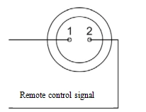 Fig. 3 Fig. 3 |
●Pulse control metering pump
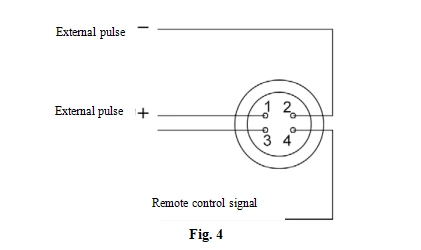
There are two interfaces of pulse control metering pump: Pulse control interface and remote start/stop control interface (option).
Pulse control interface: The interface signal is active pulse signal or passive switch signal.
Remote control interface: The interface signal is dry contact switch signal, either NO or NC available for option. (See Fig. 4)
If the power source of the sensor for generating pulse signal is 5VDC, metering pump can offer this power. (See Fig. 5)
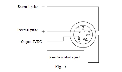
Note: If external pulse signal is active pulse signal, make sure to ensure correct anode and cathode direction. The terminal of aerial plug, numbered as 1, must be connected to anode, while the terminal of aerial plug, numbered as 2, must be connected to cathode. If the two terminals are reversely wired, the metering pump can not work normally.
●4-20mA metering pump
4-20mA metering pump has two interfaces: Current control interface and remote start/stop control interface (option).
The interface signal is dry contact switch signal, either NO or NC available for option.
Current control interface: The interface signal is standard 0/4-20mA. Specific control mode is proportional control. Proportional coefficient can be adjustable and inverse proportional control is supported. (See Fig. 6)
| Note: External current signal must be correct in electrode direction. The terminal of aerial plug, numbered as 1, must be connected to anode, while the terminal of aerial plug, numbered as 2, must be connected to cathode. If the two terminals are reversely wired, the metering pump can not work normally. |
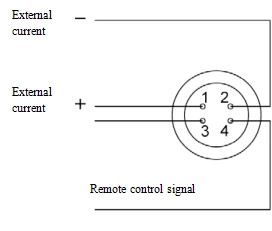 Fig. 6 Fig. 6 |
4. Pipeline Routing
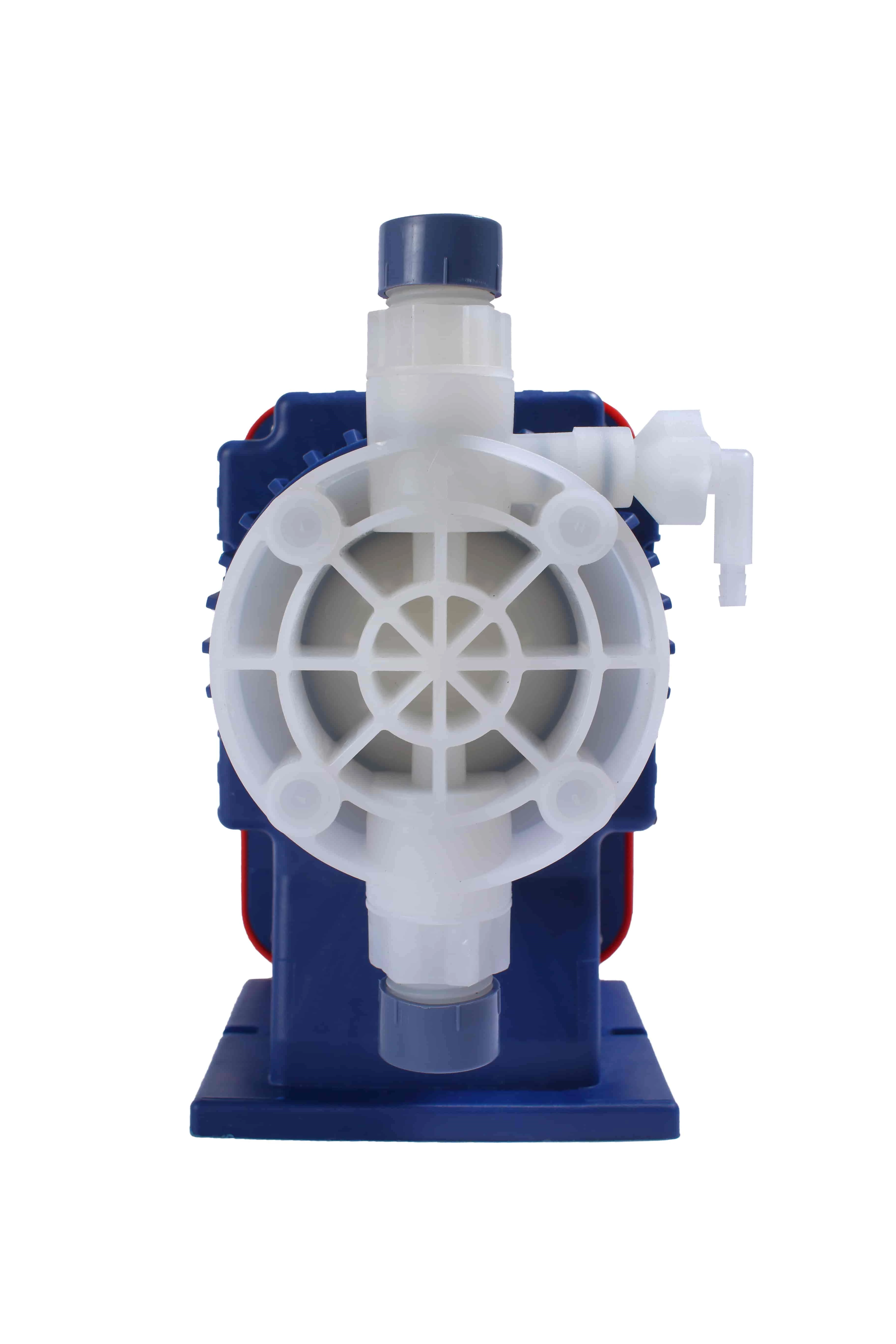
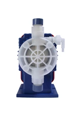
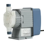
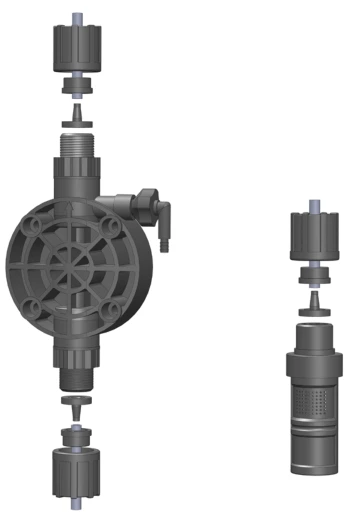
The metering pump is accompanied with one 2m suction pipe, one 2m drain pipe, a bottom valve filter and an injection valve. The suction pipe is a transparent hose, with one end connecting to bottom valve filter and the other end connecting to the inlet valve of metering pump. The drain pipe is a semi-transparent white hose, with one end connecting to the metering pump’s outlet valve and the other end connecting to injection valve. Before connecting the drain pipe to outlet valve, it’s allowed to inject a little water to the outlet valve; in this way, the exhaust time can be shortened. (See Fig. 7)
Start and Commissioning
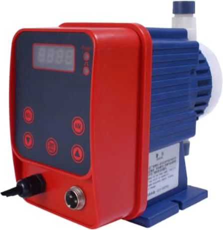
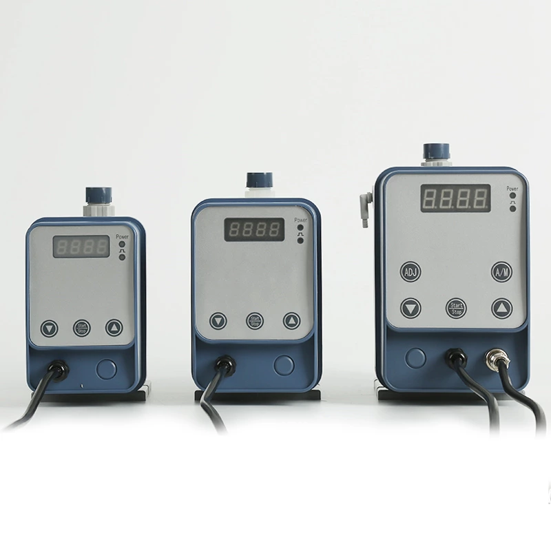
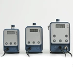
1. Commissioning of Manual Metering Pump
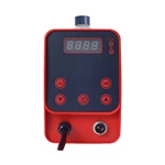
Distribution of manual metering pump’s panel buttons and indicators. (See Fig. 8) Power indicator: Power indicator  indicator: Working indicator Start/Stop: On/off button indicator: Working indicator Start/Stop: On/off button  : Numerical increase button : Numerical increase button  : Numerical decrease button ●Turn on the power of the metering pump according to relevant instructions, Power indicator on. Press Start/Stop button, the metering pump starts to work; the frequency displayed by panel is the metering pump’s working frequency. If the last bit “H” of nixie tube flickers, it indicates the stop status; if the last bit “H” does not flicker, it indicates the working status. ●Pressing △ or ▽could adjust the output flow of metering pump. : Numerical decrease button ●Turn on the power of the metering pump according to relevant instructions, Power indicator on. Press Start/Stop button, the metering pump starts to work; the frequency displayed by panel is the metering pump’s working frequency. If the last bit “H” of nixie tube flickers, it indicates the stop status; if the last bit “H” does not flicker, it indicates the working status. ●Pressing △ or ▽could adjust the output flow of metering pump. |
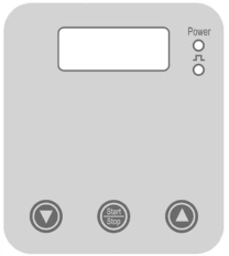 Fig. 8 Fig. 8 |
2. Commissioning of Pulse Metering Pump
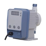
Distribution of pulse metering pump’s panel buttons and indicators. (See Fig. 9) Power indicator: Power indicator  indicator: Working indicator Start/Stop: On/off button ADJ: Function button A/M: Manu/Auto switching button indicator: Working indicator Start/Stop: On/off button ADJ: Function button A/M: Manu/Auto switching button  : Numerical increase button : Numerical increase button  : Numerical decrease button : Numerical decrease button |
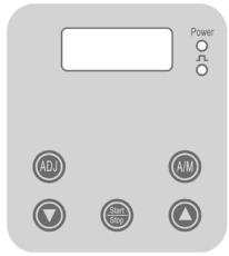 Fig. 9 Fig. 9 |
●Turn on the power of the metering pump according to relevant instructions, Power indicator on. Press Start/Stop button, the metering pump starts to work; the frequency displayed by panel is the metering pump’s working frequency. Working modes can be switched over by pressing A/M button for 3s. The last bit “H” of nixie tube indicates manual mode; if the last bit flickers, it indicates the stop status; if the last bit does not flicker, it indicates the working status.
●See 4.1 for manual parameter setting.
●When metering pump is in auto mode, flow can be adjusted according to the pulse frequency inputted externally.
●This series of metering pumps have the functions of frequency division and frequency multiplication. Under automatic mode, pressing “ADJ” button and “A/M” button could enter the frequency division and frequency multiplication function menu:
First parameter display: 0011 Multiplication factor
Pressing Start/Stop to enter:
Second parameter display: 0012 Division factor
Pressing Start/Stop button to return:
Pressing  or
or  to change set factor.
Note: Permissible external pulse signal’s maximum frequency is 200Hz. For active pulse signal, high-level voltage range: 1.5 - 2.4V. Connecting signal not matching the metering pump may cause damage to the pump and such damage is not in the warranty scope of the manufacturer.
3. Commissioning of 4-20mA Metering Pump
Distribution of 4-20mA control metering pump’s panel buttons and indicators. (See Fig. 9)
Power indicator: Power indicator
 indicator: Working indicator
Start/Stop: On/off button
ADJ: Function button
A/M: Manu/Auto switching button
 : Numerical increase button
 : Numerical decrease button
●Turn on the power of the metering pump according to relevant instructions, Power indicator on. Press Start/Stop button, the metering pump starts to work; the frequency displayed by panel is the metering pump’s working frequency. Working modes can be switched over by pressing A/M button for 3s. The last bit “H” of nixie tube indicates manual mode and “P” of nixie tube indicates auto mode. if the last bit flickers, it indicates the stop status; if the last bit does not flicker, it indicates the working status.
●See 4.1 for manual parameter setting.
●When metering pump is in auto mode, flow can be adjusted automatically depending on the 4-20mA signal inputted externally.
●Under automatic mode, pressing “ADJ” button and “A/M” button simultaneously could enter the frequency division and frequency multiplication function menu:
First parameter display: 0041 Start control current 4mA
Pressing Start/Stop to enter:
Second parameter display: 0202 End control current 20mA
Pressing Start/Stop to enter:
Third parameter display: 0003 Frequency corresponding to start control current
Pressing Start/Stop to enter:
Fourth parameter display: 1204 Frequency corresponding to end control current
Pressing Start/Stop button to return.
Pressing  or
or  to change set factor.
●When the set value of the third parameter is greater than that of the fourth parameter, metering pump can realize inverse proportional control.
Routine Maintenance
●Check the pump’s working status regularly. Check if there is any phenomenon such as abnormal sound, excessive vibration/flow/pressure or low/high temperature [if the pump always runs at maximum travel speed, pump case temperature can reach up to 160 ℃(70°F)].
● To obtain optimum performance, one-way valve should be replaced once every 4 to 6 months. More frequent change may be required for specific applications. If the service life of valve seat and valve ball is short repeatedly or aging easily, check if over current components material for the application is applicable. For any help, please contact manufacturer.
● Check connectors to see if there is any leakage around them or of aged pipeline. If so, proper measures shall be taken, for example tightening connectors or replacing components whenever necessary.
● Clean away any dirt/scrap on the pump, because such substance can be heat insulating and result in excessively high temperature.
● If the pump has been left unused for more than 1 month, clean pump head and valve component. The method of cleaning is pumping fresh water for about 30min. If the pump can not work normally yet after the cleaning, it’s necessary to replace the insertion valve component.
Common Faults and Solutions
| Fault description |
Cause |
Solution |
| Unable for automatic pump filling |
Air leak at suction end |
Check if suction end’s seals are proper and replace seal ring whenever necessary |
| Suction lift of pump fluid too high |
Reduce the installation height of pump |
| Excessively high medium viscosity and density |
Immersion installation adopted |
| Excessively high pressure at outlet |
Open exhaust valve |
| Blockage of filter of bottom valve |
Clean the filter |
| Too low flow |
Pump’s rated pressure is less than system pressure |
Replace the pump with a metering pump of appropriately higher pressure |
| Poor sealing effect of one-way valve |
Clean or replace one-way valve |
| Bottom valve and injection valve blocked |
Clean inlet or outlet pipeline |
| Electromagnet spring broken |
Replace it with a new one |
| Too high medium viscosity |
Replace the metering pump with a new one; contact manufacturer |
| Too high flow |
Siphon action |
Add anti-siphon valve to outlet pipeline |
| The pressure at injection point is far less than the pump’s rated pressure |
Replace the pump with a metering pump of small flow |
| Pump does not work |
Power indicator not on |
Problem of power supply |
Check power supply circuit |
| Built-in fuse of pump control panel burnt down |
Replace the fuse |
| Working indicator not on |
Control panel’s component burnt down |
Replace the control panel |
| Working indicator normally on |
Control panel’s component burnt down |
Replace the control panel |